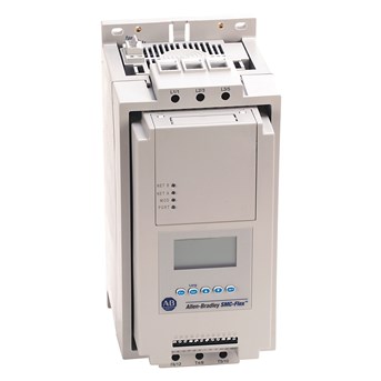
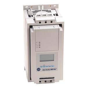
Detail ALLEN BRADLEY PLC (Programmable Logic Controller)-150-F135NBD
PLC (Programmable Logic Controller)
Technical Specifications
Electrical
With display
Yes
Voltage type for actuating
AC
Rated operating voltage Ue
200 V
Rated control supply voltage at AC 50 Hz
100 V
Rated control supply voltage at AC 60 Hz
100 V
Overload current for line connected devices
34 A
Overload current for delta connected devices
59 A
Controller type
Soft starter
Control options
None
Trip classes
10, 15, 20 and 30
Trip current rating
117% of motor FLC
Transformer control module
75VA @ 100...240V AC (-15%, +10%)
Heatsink fan rating
20VA @ 110/120V AC or 220/240V AC
DV/DT protection
RC snubber network for power circuit
Repetitive peak inverse voltage rating
1400V per UL/CSA/NEMA for power circuit
Operating frequency
50/60 Hz for power circuit
Line connected motor power, max
90 kW @ 500V AC, 50 Hz, 3-phase
Delta connected motor power, max
75 kW @ 230V AC, 50 Hz, 3-phase
Rated impulse voltage
6000V per IEC for power circuit
Dielectric withstand
2500V per IEC for power circuit
Line connected motor current
34...135 A @ 600/Y/690V AC, 3-phase
Delta connected motor current
59...234 A @ 500/575V AC, 3-phase
Ampere tested european style, max
6,9 gRB 73xxx400 6,6URD33xxx500 @ 690V for maximum FLC
Ampere tested north american style, max
A070URD33xxx500 @ 690V for maximum FLC
Transient protection
Metal oxide varistors: 220 Joules (optional) for power circuit
Insulation voltage
Rated 500V per IEC for power circuit
Rated operational voltage
200...480V AC (-15%, +10%) per UL/CSA/NEMA for power circuit
Input OFF-state current
<10 mA AC, <3 mA DC for control circuit @ input OFF-state voltage
Short-circuit protection device list
Standard fuse, circuit breaker and high capacity time delay class CC/J/L
Number of contacts
1 for auxiliary contacts
High capacity available fault current, max
70 kA @ 600V, maximum current 400 A time delay Class J or Class L fuse for inside delta connected motors
Type of current
AC for auxiliary contacts
Conventional thermal current (Ith)
AC/DC: 5 A for auxiliary contacts
Type of control circuit
Electromagnetic relay for auxiliary contacts
Type of contacts
Programmable NO/NC for auxiliary contacts
Utilization category
MG 1 per UL/CSA/NEMA for power circuit
Standard controller feature
Status indication: stopped, starting, stopping, at speed, alarm and fault
Standard available fault current, max
70 kA @ 690V for maximum FLC
Optional controller feature
SMB smart motor braking control: provides motor braking without additional equipment for applications that require the motor to stop quickly, braking current is adjustable from 0...400% of the motor’s full-load current rating
Integrated motor overload protection
Yes
Short circuit protection device performance (SCPD) type
Type 1
Number of sensors, max
6 for PTC input ratings
Inrush current control module
5 A @ 24V DC (-15%, +10%)
Voltage at PTC terminals (RPTC = open), max
30V for PTC input ratings
Transient watts control module
60 W @ 24V DC (-15%, +10%)
Steady state watts control module
24 W @ 24V DC (-15%, +10%)
Voltage at PTC terminals (RPTC = 4 kΩ), max
<7.5 for PTC input ratings
Response time
800 ms for PTC input ratings
Inrush time control module
250 ms @ 24V DC (-15%, +10%)
Transient time control module
500 ms @ 24V DC (-15%, +10%)
Cold resistance of PTC sensor chain, max
1500 Ohm for PTC input ratings
Tachometer input
0...5V DC, 4.5V DC = 100% Speed
Allen bradley power supply control module, min
1606-XLP50E @ 24V DC (-15%, +10%)
Short circuit trip resistance
25 Ohm ± 10 Ohm for PTC input ratings
Response resistance
3400 Ohm ± 150 Ohm for PTC input ratings
Reset resistance
1600 Ohm ± 100 Ohm for PTC input ratings
Input OFF-state voltage, max
50V AC, 10V DC/12V AC for control circuit
Input ON-state voltage, min
85V AC, 19.2V DC/20.4V AC for control circuit
Rated operational current
3 A @ 120V AC, 1.5 A @ 240V AC for auxiliary contacts
Input ON-state current
20 mA @ 120V AC/40mA @ 240V AC, 7.6 mA @ 24V AC/DC for control circuit
Contact type
auxiliary contacts 19/20 (Aux #1), 29/30 (Aux #2), 31/32 (Aux #3) and 33/34 (Aux #4)
Environmental
Steady state heat dissipation with control and fan power
104 W
Storage and transportation temperature
-20 °C
Humidity
5...95% (noncondensing)
Operating temperature
Open: -5 to 50 °C (23 to 122 °F)
Protection against electrical shock
IP2X (with terminal covers) per IEC for power circuit
EMC emission levels
Radiated emission: Class A
EMC immunity levels
Surge transient: per EN/IEC 60947-4-2
Altitude
2000 m
Pollution degree
2
Mechanical
Weight
15 kg
Shock
Operational: 5.5 G
Width
196.4 mm (7.74 inch)
Depth
212.2 mm (8.35 inch)
Height
443.7 mm (17.47 inch)
Power pole construction
Heatsink hockey puck thyristor modular design
Vibration
Operational: 1.0 G peak, 0.15 mm (0.006 inch) displacement
Make
3600VA for auxiliary contacts
Break
360VA for auxiliary contacts
Internal bypass
Yes
Function
Single direction
Power terminal markings
NEMA, CENELEC EN50 012
Control terminals
Clamping yoke connection, M3 screw clamp
Construction
Line/load side power terminals
One M10 x 1.5 diameter hole per power pole
Number of poles
3
Enclosure
Open type
Control modules construction
Thermoset and thermoplastic moldings
Metal parts construction
Plated brass, copper or painted steel
Tampilkan Lebih Banyak